
This is Sue Jang
Building a processor (3) - Instruction array 본문
Engineering courses/Digital System Design
Building a processor (3) - Instruction array
Suyun 2023. 10. 26. 07:27Making the instruction array, registers, and testing with the realterm.
Design Sources
// top module
module Instruction_memory_test(
    input CLK,
    input UART_TXD_IN,
    input [15:0] SW,
    output  [7:0] CA,AN,
    output  [15:0] LED
    );

wire [15:0] instruction;

Instruction_memory i_mem(.CLK(CLK),.UART_TXD_IN(UART_TXD_IN),
                          .program_counter(SW[15:11]), .load_done(LED[15]),
                          .instruction(instruction));
ssegx8 display ( .CLK(CLK), .VALUE({instruction,instruction}),.SSEG_CA(CA),.SSEG_AN(AN));

endmodule
module Instruction_memory(
input CLK,
input UART_TXD_IN,
input [4:0] program_counter,
output reg load_done=0,
output reg [15:0] instruction
);
reg state=0;
reg [4:0] write_addr=0;
reg [15:0] instruction_array [31:0];
wire [7:0] o_data;
wire o_wr;
rxuartlite uart (.i_clk(CLK),.i_uart_rx(UART_TXD_IN),.o_wr(o_wr), .o_data(o_data));
always @(posedge CLK)
begin
instruction<=instruction_array[program_counter];
if (o_wr==1 &&load_done==0)
begin
case (state)
0:begin
instruction_array[write_addr][15:8]<=o_data;
state<=1;
end
1: begin
instruction_array[write_addr][7:0]<=o_data;
state<=0;
write_addr<=write_addr+1;
if (write_addr==31)
begin
load_done<=1;
end
end
endcase
end
end
endmodule////////////////////////////////////////////////////////////////////////////////
//
// Filename: rxuartlite.v
//
// Project: wbuart32, a full featured UART with simulator
//
// Purpose: Receive and decode inputs from a single UART line.
//
//
// To interface with this module, connect it to your system clock,
// and a UART input. Set the parameter to the number of clocks per
// baud. When data becomes available, the o_wr line will be asserted
// for one clock cycle.
//
// This interface only handles 8N1 serial port communications. It does
// not handle the break, parity, or frame error conditions.
//
//
// Creator: Dan Gisselquist, Ph.D.
// Gisselquist Technology, LLC
//
////////////////////////////////////////////////////////////////////////////////
//
// Copyright (C) 2015-2019, Gisselquist Technology, LLC
//
// This program is free software (firmware): you can redistribute it and/or
// modify it under the terms of the GNU General Public License as published
// by the Free Software Foundation, either version 3 of the License, or (at
// your option) any later version.
//
// This program is distributed in the hope that it will be useful, but WITHOUT
// ANY WARRANTY; without even the implied warranty of MERCHANTIBILITY or
// FITNESS FOR A PARTICULAR PURPOSE. See the GNU General Public License
// for more details.
//
// You should have received a copy of the GNU General Public License along
// with this program. (It's in the $(ROOT)/doc directory. Run make with no
// target there if the PDF file isn't present.) If not, see
// <http://www.gnu.org/licenses/> for a copy.
//
// License: GPL, v3, as defined and found on www.gnu.org,
// http://www.gnu.org/licenses/gpl.html
//
//
////////////////////////////////////////////////////////////////////////////////
//
//
//`default_nettype none
//
`define RXUL_BIT_ZERO 4'h0
`define RXUL_BIT_ONE 4'h1
`define RXUL_BIT_TWO 4'h2
`define RXUL_BIT_THREE 4'h3
`define RXUL_BIT_FOUR 4'h4
`define RXUL_BIT_FIVE 4'h5
`define RXUL_BIT_SIX 4'h6
`define RXUL_BIT_SEVEN 4'h7
`define RXUL_STOP 4'h8
`define RXUL_WAIT 4'h9
`define RXUL_IDLE 4'hf
module rxuartlite(i_clk, i_uart_rx, o_wr, o_data);
parameter TIMER_BITS = 10;
`ifdef FORMAL
parameter [(TIMER_BITS-1):0] CLOCKS_PER_BAUD = 16; // Necessary for formal proof
`else
parameter [(TIMER_BITS-1):0] CLOCKS_PER_BAUD = 868; // 115200 MBaud at 100MHz
`endif
localparam TB = TIMER_BITS;
input wire i_clk;
input wire i_uart_rx;
output reg o_wr;
output reg [7:0] o_data;
wire [(TB-1):0] half_baud;
reg [3:0] state;
assign half_baud = { 1'b0, CLOCKS_PER_BAUD[(TB-1):1] };
reg [(TB-1):0] baud_counter;
reg zero_baud_counter;
// Since this is an asynchronous receiver, we need to register our
// input a couple of clocks over to avoid any problems with
// metastability. We do that here, and then ignore all but the
// ck_uart wire.
reg q_uart, qq_uart, ck_uart;
initial q_uart = 1'b1;
initial qq_uart = 1'b1;
initial ck_uart = 1'b1;
always @(posedge i_clk)
{ ck_uart, qq_uart, q_uart } <= { qq_uart, q_uart, i_uart_rx };
// Keep track of the number of clocks since the last change.
//
// This is used to determine if we are in either a break or an idle
// condition, as discussed further below.
reg [(TB-1):0] chg_counter;
initial chg_counter = {(TB){1'b1}};
always @(posedge i_clk)
if (qq_uart != ck_uart)
chg_counter <= 0;
else if (chg_counter != { (TB){1'b1} })
chg_counter <= chg_counter + 1;
// Are we in the middle of a baud iterval? Specifically, are we
// in the middle of a start bit? Set this to high if so. We'll use
// this within our state machine to transition out of the IDLE
// state.
reg half_baud_time;
initial half_baud_time = 0;
always @(posedge i_clk)
half_baud_time <= (!ck_uart)&&(chg_counter >= half_baud-1'b1-1'b1);
initial state = `RXUL_IDLE;
always @(posedge i_clk)
if (state == `RXUL_IDLE)
begin // Idle state, independent of baud counter
// By default, just stay in the IDLE state
state <= `RXUL_IDLE;
if ((!ck_uart)&&(half_baud_time))
// UNLESS: We are in the center of a valid
// start bit
state <= `RXUL_BIT_ZERO;
end else if ((state >= `RXUL_WAIT)&&(ck_uart))
state <= `RXUL_IDLE;
else if (zero_baud_counter)
begin
if (state <= `RXUL_STOP)
// Data arrives least significant bit first.
// By the time this is clocked in, it's what
// you'll have.
state <= state + 1;
end
// Data bit capture logic.
//
// This is drastically simplified from the state machine above, based
// upon: 1) it doesn't matter what it is until the end of a captured
// byte, and 2) the data register will flush itself of any invalid
// data in all other cases. Hence, let's keep it real simple.
reg [7:0] data_reg;
always @(posedge i_clk)
if ((zero_baud_counter)&&(state != `RXUL_STOP))
data_reg <= { qq_uart, data_reg[7:1] };
// Our data bit logic doesn't need nearly the complexity of all that
// work above. Indeed, we only need to know if we are at the end of
// a stop bit, in which case we copy the data_reg into our output
// data register, o_data, and tell others (for one clock) that data is
// available.
//
initial o_wr = 1'b0;
initial o_data = 8'h00;
always @(posedge i_clk)
if ((zero_baud_counter)&&(state == `RXUL_STOP)&&(ck_uart))
begin
o_wr <= 1'b1;
o_data <= data_reg;
end else
o_wr <= 1'b0;
// The baud counter
//
// This is used as a "clock divider" if you will, but the clock needs
// to be reset before any byte can be decoded. In all other respects,
// we set ourselves up for CLOCKS_PER_BAUD counts between baud
// intervals.
initial baud_counter = 0;
always @(posedge i_clk)
if (((state==`RXUL_IDLE))&&(!ck_uart)&&(half_baud_time))
baud_counter <= CLOCKS_PER_BAUD-1'b1;
else if (state == `RXUL_WAIT)
baud_counter <= 0;
else if ((zero_baud_counter)&&(state < `RXUL_STOP))
baud_counter <= CLOCKS_PER_BAUD-1'b1;
else if (!zero_baud_counter)
baud_counter <= baud_counter-1'b1;
// zero_baud_counter
//
// Rather than testing whether or not (baud_counter == 0) within our
// (already too complicated) state transition tables, we use
// zero_baud_counter to pre-charge that test on the clock
// before--cleaning up some otherwise difficult timing dependencies.
initial zero_baud_counter = 1'b1;
always @(posedge i_clk)
if ((state == `RXUL_IDLE)&&(!ck_uart)&&(half_baud_time))
zero_baud_counter <= 1'b0;
else if (state == `RXUL_WAIT)
zero_baud_counter <= 1'b1;
else if ((zero_baud_counter)&&(state < `RXUL_STOP))
zero_baud_counter <= 1'b0;
else if (baud_counter == 1)
zero_baud_counter <= 1'b1;
endmodulemodule ssegx8(
input CLK,
input [31:0] VALUE,
output reg [7:0] SSEG_CA,
output reg [7:0] SSEG_AN
);
reg [20:0] digit_counter;
reg [3:0] digits;
always @(posedge CLK)
begin
digit_counter<=digit_counter+1;
case (digits)
// pgfedcba
0:SSEG_CA = 8'b11000000;
1:SSEG_CA = 8'b11111001;
2:SSEG_CA = 8'b10100100;
3:SSEG_CA = 8'b10110000;
4:SSEG_CA = 8'b10011001;
5:SSEG_CA = 8'b10010010;
6:SSEG_CA = 8'b10000010;
7:SSEG_CA = 8'b11111000;
8:SSEG_CA = 8'b10000000;
9:SSEG_CA = 8'b10010000;
10:SSEG_CA=~8'b11110111;
11:SSEG_CA=~8'b11111100;
12:SSEG_CA=~8'b10111001;
13:SSEG_CA=~8'b11011110;
14:SSEG_CA=~8'b11111001;
15:SSEG_CA=~8'b11110001;
endcase
case (digit_counter[16:14])
0 : begin
SSEG_AN=8'b01111111;
digits<=VALUE[31:28];
end
1 : begin
SSEG_AN=8'b10111111;
digits<=VALUE[27:24];
end
2 : begin
SSEG_AN=8'b11011111;
digits<=VALUE[23:20];
end
3 : begin
SSEG_AN=8'b11101111;
digits<=VALUE[19:16];
end
4 : begin
SSEG_AN=8'b11110111;
digits<=VALUE[15:12];
end
5 : begin
SSEG_AN=8'b11111011;
digits<=VALUE[11:8];
end
6 : begin
SSEG_AN=8'b11111101;
digits<=VALUE[7:4];
end
7 : begin
SSEG_AN=8'b11111110;
digits<=VALUE[3:0];
end
endcase
end
endmodule
Realterm
// Text file to upload
// 32 letters for 32 bits

abcdefghijklmnopqrstuvwxyzABCDEFGHIJKLMNOPQRSTUVWXYZ01234567890!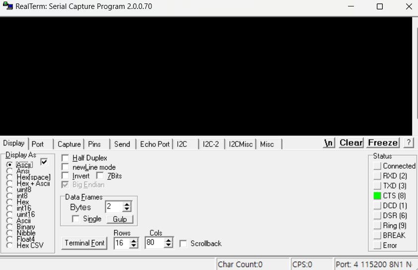


Result

- Because of this code(ssegx8 display ( .CLK(CLK), .VALUE({instruction, instruction}),.SSEG_CA(CA),.SSEG_AN(AN));) from 'module ssegx8', the VALUE is repeated twice. 'instruction' is 16bits and 'VALUE' is 32bits. Each segment is 4 bits.
- ASCII 61 and 62 are 'a' and 'b'.


- ASCII 63 and 64 are 'c' and 'd'.

- ASCII 30 and 21 are '0' and '!'.
'Engineering courses > Digital System Design' 카테고리의 다른 글
| Building a processor (4) - Assembly language (0) | 2023.11.04 |
|---|---|
| Building a processor (2) - ALU control (1) | 2023.10.26 |
| Building a Processor (1) - Basic Information (0) | 2023.10.26 |
| Amplitude Modulation (1) | 2023.10.17 |
| Debouncing (0) | 2023.10.06 |
'Engineering courses/Digital System Design' Related Articles
more


